1124 49 kb transformer wiring diagram l. In this topic you study Autotransformer Starter Working Diagram.

Auto Transformer Starter Your Electrical Guide
September 19th 2018 - The phasor diagram of operation for the auto transformer drawing a load current at a lagging power factor angle of 2 is shown in Fig All.

. This may cause excessive strain on the motor and creates an intense voltage dip. Let Z e10 is the equivalent standstill impedance per phase of the motor referred to the stator side. Figure a shown below represents the condition when the motor is directly switched on to lines and figure b shows when the motor is started with the help of an autotransformer.
When the setting time on the timer has expired the autotransformer is bypassed. Wiring Diagram For Massey Ferguson 135 Tractor. Circuit and Working Principle of Autotransformer Starter.
This motor starting method has been updated and improved by Hilton Raymond Bacon. I B Make a list of components used. View Images Library Photos and Pictures.
Figure 2 B Make a list of components used. Motors of these power ratings draw excessive starting current with the use of StarDelta starter. Drawing The Schematic Diagram Of Autotransformer Starter.
The operation of the autotransformer starter will be like this. The ABB autotransformer starter is a closed transition type meaning that the motor remains connected to the. HowTo Draw - Auto transformer Starter Circuit Diagram.
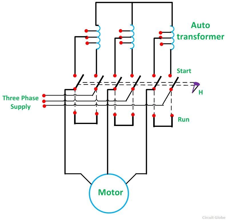
2 It is used for large motors in which start by direct connection to the network is not possible. Auto Transformer Starter3 Cdr. When the switch is in the starting position the Stator of an induction motor is supplied with reduced voltage through the auto-transformer using suitable tap.
929 49 kb transformer wiring diagram c. Autotransformer And Variable Auto Transformer. Autotransformer Starter A Reduced Voltage Motor Starting.
1124 58 kb transformer wiring diagram m0n acme. Q2A Draw the schematic diagram for an Autotransformer Starter for a Three Phase Induction Motor. 506 90 kb transformer wiring diagram d.
For large motors also the star-delta starter cannot be used especially if they are started with a significant load. Operation of a practical autotransformer starter. Autotransformer Starter Diagram Working Explaination.
Component 1 2 3 3 4 5 c Write the relationship between line currents of the motor and the line at start. Transformer wiring diagram b. Wiring Diagram For Auto Transformers All Diagram Schematics.
519 56 kb transformer wiring diagram a. Motor Starter Wiring Simulation Wiring Diagram Rows. To activate the motor the two switches in the circuit like 1 2 are closed.
Auto transformer starters are used generally with AC squirrel cage motors having a power rating of more than 20 HP. Typical Circuit Diagram For Auto Transformer Starter. Figure 2 B Make a list of components used.
Using The Schematic Diagram In Figure 20 23 Determine The. The autotransformer starter can be used for starting both star and delta connected 3-phase induction motors. I B Make a list of components used.
Direct On Line Dol Motor Starter Schematic Of The Power Circuit Of Electro Pump Starter Via Automatic Download Scientific Diagram Advantages Of Soft Start Motor Control Wiring Circuit For A Contractor Wiring Diagram Brown Corsa E Brown Corsa E Pasticceriagele It. Draw The Schematic Diagram Of Autotransformer Starter. Once the switches are closed then less voltage can be supplied to the motor from the.
Star Delta Motor Starter Explained In Details Eep Diagram Wiring Diagram Starter Dol Full Version Hd Quality Starter Dol Cbschematic2b Angelux It What Is Auto Transformer Starter Its Theory Circuit Globe Drawing The Schematic Diagram Of Autotransformer Starter Dol Starter And Star Delta Starter Youtube. Drawing the schematic diagram of Autotransformer starter DOL starter and Star Delta StarterDrawing development diagram dcsimplex lapwave with brush posit. In electrical engineering the Korndorfer starter is a technique used for reduced voltage soft starting of induction motors.
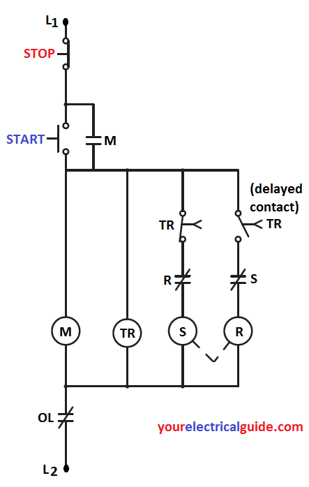
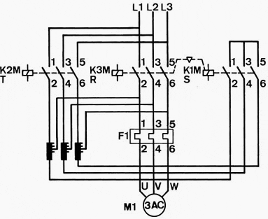
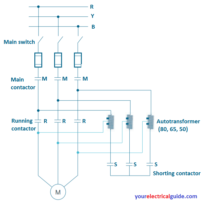
They are the start contactor S main contactor M and the run contactor R. 4 Typical Circuit Diagram. TYPICAL CIRCUIT DIAGRAM FOR AUTO TRANSFORMER STARTER INTERNAL CONNECTION DIAGRAM FOR DC COIL CIRCUITS K1 SIZES 3 TO 6 3TF46 TO 3TF51 K1 SIZES 8 TO 12Theory Of Operation.
The circuit uses a three-phase autotransformer and three three-phase switches. Readers are encouraged to identify these in the figure below. Unlike the star delta connection only three motor wires and terminals are required.
View Images Library Photos and Pictures. In both cases I 1 is the input current and I 2 is output current Regardless of Step UpStepdown autotransformer the current in the section of winding that is common to both the primary and secondary is the difference between these two currents I 1 and I 2. By reducing the voltage the current drawn from the line is reduced during start-up.
Advantages Auto transformer starter. 1 The autotransformer starter limits significantly the inrush current. Theory of Autotransformer Starter.
Schematic of an auto transformer starter is shown below. Auto Mobile Schematic Diagram Wiring Diagram Rows. In this method the starting current of the motor is limited by using a 3-phase.
Q2A Draw the schematic diagram for an Autotransformer Starter for a Three Phase Induction Motor. 14 Best Auto Transformer Images Auto Transformer. Working Principle Of Autotransformer Your Electrical Guide.
V 1 is the supply voltage per phase. The circuit diagram of an autotransformer starter for starting a 3-phase induction motor is shown in the figure. Autotransformer what is it auto transformer starter your an working circuit globe starting motor with learn about overview javatpoint electrical how works to solved 13 the control for starters diagram of three circuits decompression variable voltage theory advantages magnetic gig 3 phase star design.
An autotransformer starter reduces inrush current by using a transformer in the line just ahead of the motor to step down the voltage applied to the motor terminals. The circuit diagram of the autotransformer is shown below where the starter switches are represented with 1 2 and 3. A quick and easy way to draw.
Drawing the schematic diagram of autotransformer starter. There are three main contactors that play critical role in auto transformer reduced voltage starting. A three phase star-connected auto-transformer along with a suitable change-over switch forms an auto-transformer starter Fig.
The auto-transformer starter allows you to start the protein cells induction engines with a reduced starting current as the voltage throughout the engine decreases during launch. Autotransformer Starter Your Electrical Home. The above diagram depicts the connections of the loaded step-down and step-up autotransformer.

Starting Motor With Auto Transformer

Autotransformer What Is It Definition Theory Diagram Electrical4u

Autotransformer Starter Diagram Parts Working Principle Etechnog

Auto Transformer Starter Diagram Explanation In English Youtube

What Is Auto Transformer Starter Working Principle Diagram Advantages


0 comments
Post a Comment